


21.10.2025
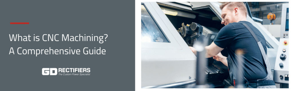
What is CNC Machining? A Comprehensive Guide
Discover what CNC machining is, how it works, the different types, tolerances, software, materials, and why GD Rectifiers’ CNC machining services are trusted across industries
CNC machining has transformed the way manufacturers create components with high precision, repeatability and efficiency. From aerospace and automotive to medical devices and power electronics, CNC (Computer Numerical Control) technology enables engineers to produce intricate parts that meet strict specifications.
At GD Rectifiers, we not only specialise in power electronics but also offer CNC machining services to meet the needs of customers requiring high-quality, bespoke components. This guide explores everything you need to know about CNC machining, from what it is and how it works to the materials used, software involved, tolerances, and our own capabilities.
What is CNC Machining?
CNC machining is a subtractive manufacturing process that uses pre-programmed computer software to control the movement of tools and machinery. Unlike manual machining, where an operator controls cutting tools, CNC machining automates the process by converting design files into precise cutting instructions.
The result is highly accurate components with repeatable quality, whether producing a single prototype or large-scale batch manufacturing. CNC machining is valued for:
- Precision — parts manufactured to microns
- Repeatability — identical results in every batch
- Flexibility — suitable for prototypes, custom parts, or large-volume runs
- Material versatility — metals, plastics, composites, and more
What does CNC stand for?
CNC stands for Computer Numerical Control.
This term describes the process of controlling machining equipment with computerised instructions. These instructions are typically derived from CAD (Computer-Aided Design) models, converted into CAM (Computer-Aided Manufacturing) code, and then translated into G-code, which guides the machine’s movement, tool paths, and cutting actions.
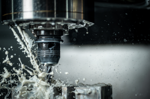
How CNC Machining Works
CNC machining follows a structured workflow:
- Design stage (CAD): Engineers create a 2D or 3D model of the component using CAD software.
- Programming stage (CAM): The design is translated into CAM software, which generates G-code — the language CNC machines understand.
- Machine setup: Operators select the appropriate tools, fixtures, and raw material stock.
- Machining process: The CNC machine executes programmed instructions, cutting, drilling, or shaping the part.
- Inspection and quality control: Parts are measured against tolerances to ensure compliance.
Automation means faster production with reduced human error, making CNC machining ideal for industries that demand accuracy and efficiency.
Types of CNC Machining
Different machining processes are available, depending on the geometry, material, and application of the part. The most common types include:
- CNC Milling
- Uses rotating cutting tools to remove material.
- Suitable for creating slots, pockets, threads, and complex 3D shapes.
- Multi-axis CNC mills (3, 4, 5-axis) enable greater part complexity.
- CNC Turning
- Involves rotating the workpiece while cutting tools move linearly.
- Ideal for cylindrical or round parts such as shafts, pins, and bushings.
- Lathes are the primary machines used for CNC turning.
- CNC Drilling
- Specialised for creating accurate holes of specific depths and diameters.
- Commonly used for fasteners, thread holes, and assembly features.
- CNC Routing
- Similar to milling but typically used for softer materials such as wood, plastics, and composites.
- Common in signage, furniture making, and lightweight components.
- CNC Cutting
- Includes plasma cutting, laser cutting, and waterjet cutting.
- Suitable for sheet materials and high-speed precision cutting.
Each machining type has its own strengths, and many components require a combination of milling, turning, and drilling.
Tolerances in CNC Machining
Tolerances define how much deviation is acceptable from the design dimensions. In CNC machining, tolerances are typically expressed in ± values (e.g., ±0.01mm).
- Standard tolerances: ±0.1mm for general machining.
- Tight tolerances: ±0.01mm for precision applications (aerospace, medical, electronics).
Tighter tolerances often increase machining time and cost, so balancing performance requirements with budget is crucial.
Geometric Tips for CNC Machining
When designing parts for CNC machining, consider the following geometric best practices:
- Avoid unnecessary complexity: Simpler geometries reduce cost and machining time.
- Wall thickness: Maintain walls thicker than 0.8mm (for metals) to avoid warping.
- Hole depth: Limit hole depths to 10x the diameter for optimal machining.
- Corner radii: Use larger radii where possible; sharp corners increase tool wear.
- Undercuts and deep pockets: Avoid unless essential, these require specialised tooling.
Good design-for-manufacture (DFM) principles ensure parts can be machined efficiently while maintaining structural integrity.
CNC Software
CNC machining relies heavily on software to translate designs into machine-readable code. Key categories include:
- CAD (Computer-Aided Design): Tools like AutoCAD, SolidWorks, Fusion 360 for part design.
- CAM (Computer-Aided Manufacturing): Converts CAD models into G-code (e.g., Mastercam, Fusion 360 CAM).
- Simulation software: Verifies tool paths and prevents collisions before machining.
- Machine control software: Interfaces directly with the CNC machine to execute instructions.
Software advancements allow for faster prototyping, reduced errors, and better integration between design and production.
Key Machining Parameters and Terminology
Understanding machining parameters helps optimise CNC operations.
- Feed rate: Speed at which the cutting tool moves relative to the workpiece.
- Spindle speed (RPM): Rotational speed of the cutting tool or workpiece.
- Depth of cut: Thickness of material removed in one pass.
- Toolpath: Predefined path that the cutting tool follows.
- Coolant/lubrication: Fluids used to reduce heat, friction, and tool wear.
- Workholding: Fixtures, chucks, or vises used to secure the material.
Optimising these parameters reduces tool wear, improves surface finish, and ensures consistent part quality.
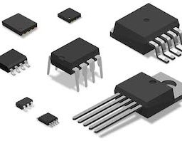
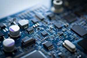
Materials for CNC Machining
CNC machines can process a wide variety of materials. The choice depends on the application, mechanical properties, and cost.
Metals
- Aluminium: Lightweight, corrosion-resistant, widely used in aerospace and electronics.
- Steel: Strong, durable, suitable for automotive and heavy machinery.
- Stainless steel: Corrosion-resistant, ideal for medical and marine applications.
- Brass & copper: Excellent conductivity, used in electrical components.
- Titanium: High strength-to-weight ratio, critical for aerospace and defence.
Plastics
- ABS, Nylon, PEEK, Polycarbonate: Lightweight and chemically resistant, common in prototypes and consumer products.
Composites and others
- Carbon fibre composites, wood, foams, ceramics for specialised applications.
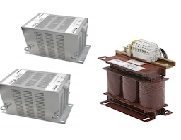
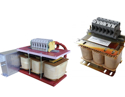
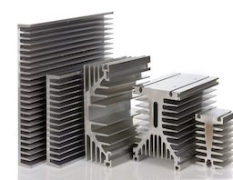
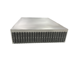
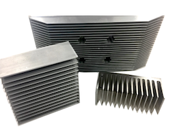
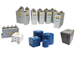
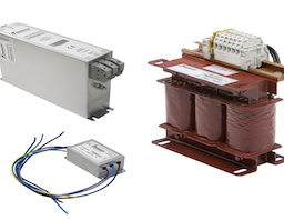
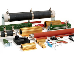
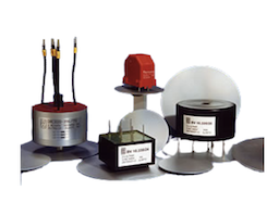
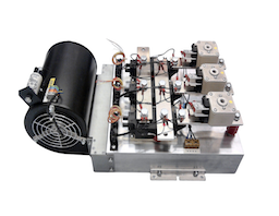
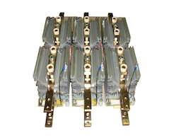
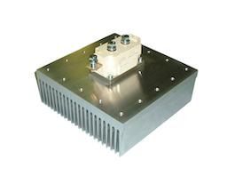
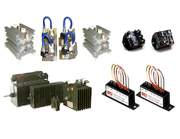
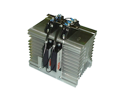
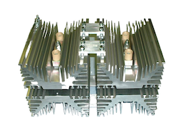
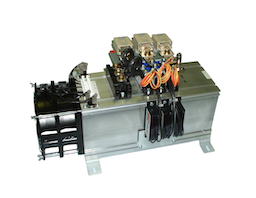
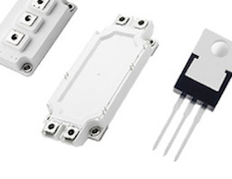
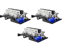
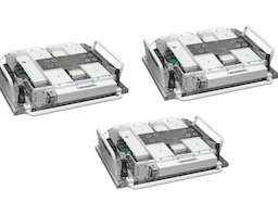
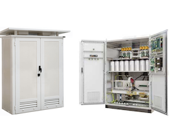
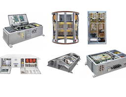
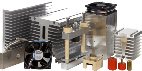
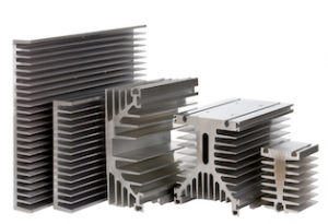
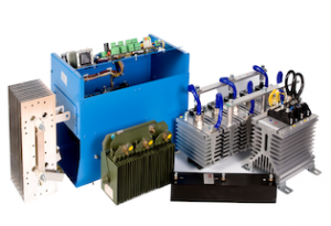
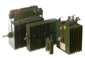
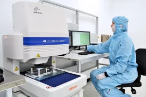
GD Rectifiers’ CNC Machining Services
At GD Rectifiers, we go beyond supplying power electronic components by offering CNC machining services for industries that require bespoke, precision parts.
Our CNC capabilities include:
- CNC milling machines that skim, drill and tap — a wide range of metals and plastics.
- Prototyping and batch production — from one-off designs to high-volume runs.
- Tight tolerances and precision finishing — for demanding applications.
- Integration with assemblies — machining parts to work seamlessly with power semiconductor devices, heatsinks, and protection assemblies.
- Customisation — tailoring designs to meet unique engineering requirements.
CNC Machining Video
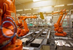
CNC Applications:
- Power electronics and assemblies
- Renewable energy (wind, solar, EV infrastructure)
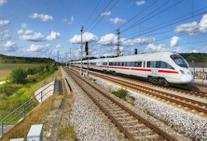
- Rail and transportation
- Aerospace and defence
- Industrial automation
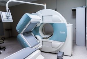
- Medical devices
By combining expertise in power semiconductors with CNC machining services, GD Rectifiers provides a unique advantage: components designed and manufactured with an understanding of their end-use in high-reliability systems.
CNC machining is a cornerstone of modern manufacturing, delivering precision, speed, and versatility across industries. Whether you need prototypes, custom components, or high-volume production, CNC technology ensures parts are made with accuracy and repeatability.
GD Rectifiers’ CNC machining services provide customers with high-quality, tailored solutions to complement our power electronics expertise. With our combination of advanced machinery, skilled engineers, and commitment to quality, we are ready to support your next project.
CNC Machining FAQs
What does CNC stand for?
CNC stands for Computer Numerical Control, the process of using computer programs to control machining equipment.
What are the main types of CNC machining?
CNC milling, turning, drilling, routing, and cutting are the most common.
What materials can be CNC machined?
Metals such as aluminium, steel, titanium, brass, and copper; plastics like ABS, PEEK, nylon; and composites including carbon fibre.
Why choose GD Rectifiers for CNC machining?
We offer tailored machining services with expertise in power electronics, ensuring high-quality, precision parts that integrate with your systems.
For further information on CNC Machining, or to discuss your CNC machining requirements, please contact our team on 01444 243 452 or email enquiries@gdrectifiers.co.uk.